Replacing The Front Rotors On My J-10

Some people may be intimidated by the thought of having to take apart a hub and replacing wheel bearings
on a front axle. Really, it's not all that difficult. With a couple of specific tools and a day in the
garage almost anyone can do this job. And the tools you need aren't all that exotic. You Just need the
following:
- A jack and jackstands
- A lug wrench
- A standard socket set
- A set of picks, available at most auto parts stores. In a pinch, you can use small screwdrivers but
picks are better for the task. If you talk to your dentist, you can often times get their used picks
that are too dull for dental work. They are just fine for automotive use.
- Snap ring pliers
- Small allen key wrench set, also called hex keys
- A 3/8" Brake Rotor allen key socket, available at most auto parts stores
- A spindle nut socket, available at most auto parts stores
- A torque wrench that reads in foot-pounds. Most spindle nut sockets are 1/2" drive but 3/8" to 1/2"
adapters are easy to find if you only have a 3/8" drive torque wrench.
- Lots of rags or paper towels to keep grease off everything and to clean up when you're done packing
grease into the bearings
- Depending on what your new hubs come with, you may need a bearing driver. You can usually rent or
borrow them at a local parts store for the day
- Of course, you need the new hubs, bearings and other parts that you're swapping. Even if you're just
checking the bearings, a new inner hub seal is needed. You have to take it out to get the bearing out.
Taking it out destroys it so you need a new replacement.
- Good quality wheel bearing grease. I used a name brand synthetic. It's not so much more expensive
but if you're counting pennies you don't need to spend the extra on synthetic. Just make sure you get
grease that is specifically made for wheel bearings. You'll want this even if you're not replacing
anything. Cleaning and repacking the bearings with fresh grease is almost mandatory in my book. The
parts are out, why not do it?
- Brake parts cleaner. Grease has a tendency to get on everything so you want to have something that
will clean it off where you really don't want it to be.
My rotor swap started with a need to replace the warped rotors in my J-10 pickup. Since this pickup uses
the Dana 44 front axle, the locking hubs are attached to the brake rotors. They aren't permanently
attached in theory. But after 24 years, I'm sure the two cast iron parts have rusted together enough
that I didn't even want to try to separate them. Besides, it's an opportunity to do a lot of additional
maintenance that should be done on a truck this old.
 I started as one would always start by loosening the lug nuts while the tire was on the ground. I then
put the axle up on jack stands. And since it involves safety, I'm a "belt and suspenders" kind of guy so
I went ahead and left the jack under the axle. If the jack stand fails, the jack may keep the truck from
crashing down. After I got the truck in the air, I removed the tire and removed the 6 screws holding the
cap in place. They use standard allen head screws and they aren't in very tight. Removing them was easy.
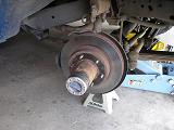
I started as one would always start by loosening the lug nuts while the tire was on the ground. I then
put the axle up on jack stands. And since it involves safety, I'm a "belt and suspenders" kind of guy so
I went ahead and left the jack under the axle. If the jack stand fails, the jack may keep the truck from
crashing down. After I got the truck in the air, I removed the tire and removed the 6 screws holding the
cap in place. They use standard allen head screws and they aren't in very tight. Removing them was easy.
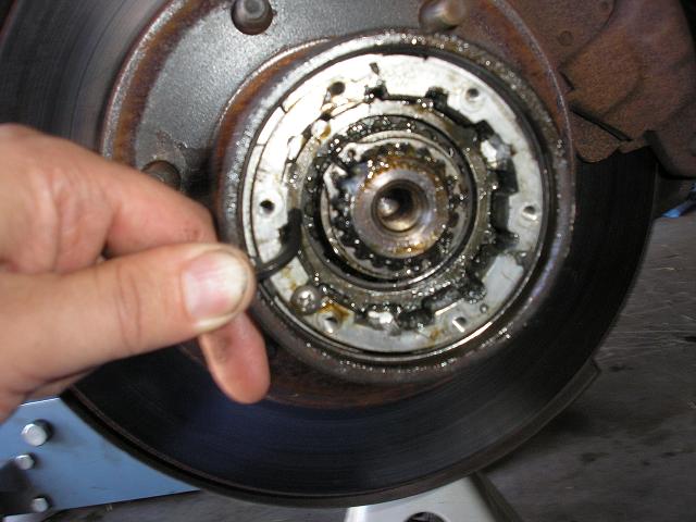
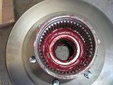
Once the screws are removed from the hub lock, it can be pulled out. If it's old, it may take some
effort to get it to pop out. It could also just fall right out without any help. Mine came out easily.
You can see the various components of the locking hub once you pull it out.
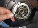
 If you don't know how a locking hub works, I'll give you a short tutorial. The working end of the
locking hub has three separate pieces. The innermost part is the hub shaft. It has splines on the
inside that mate with the axle shaft sticking out through the spindle. It always spins with the axle
shaft. In the picture, it's the part being held in by the snap ring. The outermost piece is the hub
clutch gear. It has splines on the outside which mate with the splines on the inside of the hub. It
always spins with the wheel. In the picture, it's the piece with the 6 holes for the screws that hold
the cap on. Between the hub shaft and the hub clutch gear is the clutch ring. It is only about half
as thick as the hub clutch gear and it's what moves in and out to lock and unlock the hubs. In the
picture, it's the part that you can see me pushing in.
If you don't know how a locking hub works, I'll give you a short tutorial. The working end of the
locking hub has three separate pieces. The innermost part is the hub shaft. It has splines on the
inside that mate with the axle shaft sticking out through the spindle. It always spins with the axle
shaft. In the picture, it's the part being held in by the snap ring. The outermost piece is the hub
clutch gear. It has splines on the outside which mate with the splines on the inside of the hub. It
always spins with the wheel. In the picture, it's the piece with the 6 holes for the screws that hold
the cap on. Between the hub shaft and the hub clutch gear is the clutch ring. It is only about half
as thick as the hub clutch gear and it's what moves in and out to lock and unlock the hubs. In the
picture, it's the part that you can see me pushing in.
The inside of the hub clutch gear is splined and the clutch ring has matching splines. No matter how far
you push it in, the clutch ring is always moving with the hub clutch gear. The outside of the hub shaft
has splines on it but they only cover the inner half of the of the body of the shaft. The rest is
smooth. The clutch ring has splines that will match up with the splines on the hub shaft, but only
when you push the hub shaft in. If you let the spring behind the clutch ring push it out, the splines
on the clutch ring will cover the smooth area on the hub shaft so they can spin independently.
The cap has what amounts to a screw which pushes a spring in and out when you turn it. By dialing it in,
you put enough force on the clutch ring to push it in. If the splines between the clutch ring and the
hub shaft don't line up, you can't push the clutch ring in directly. You have to rotate the tires or the
axle shaft just a little to get things to line up. The spring in the cap lets you "lock" the hubs
without everything exactly lining up. When you get back in the vehicle and start moving, the axle shaft
and wheel will rotate a little and the clutch ring will pop into place once the splines line up. And
that, in a nutshell, is how a locking hub works.
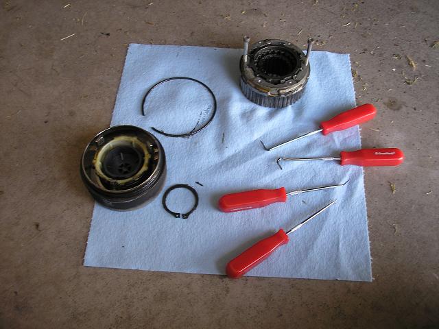
 Since the locking hub has to come out to get the brake rotor off, I used a couple of cheap picks that I
bought at a local parts store to pull the locking ring out. I used a set of snap ring pliers to pull out
the snap ring. I used two of the cap screws as handles so I could just pull the locking hub assembly
out. In the picture, you can see the locking ring in the upper left and the snap ring below it. You can
also see the inside of the cap. It's a little tough to see in the picture but you can amost see the
spring inside the cap pushing that off white piece in.
Since the locking hub has to come out to get the brake rotor off, I used a couple of cheap picks that I
bought at a local parts store to pull the locking ring out. I used a set of snap ring pliers to pull out
the snap ring. I used two of the cap screws as handles so I could just pull the locking hub assembly
out. In the picture, you can see the locking ring in the upper left and the snap ring below it. You can
also see the inside of the cap. It's a little tough to see in the picture but you can amost see the
spring inside the cap pushing that off white piece in.
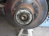
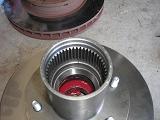
Once the hub is out, you can remove the lock nuts that hold the hub and brake rotor on. The locknuts
aren't like regular bolts. They have notches in them and they requrie a special socket to turn them.
You can fabricate something to take the place of the socket but it's easier just to get the right tool.
The socket is relatively cheap and you can find it at any parts store. The locknuts hold the bearings
in place to let the wheel spin freely. There are two bearings, an inside bearing and an outside bearing.
The inside bearing rests against the inside of the spindle while the outside bearing is in direct contact
with the locknut.
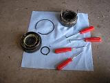
There are three pieces to the locknut assembly, the inner locknut, the retaining ring and the outer lock
nut. They have to use this arrangement to keep the locknut from working itself loose while the truck
drives down the highway. This is because the inner locknut is pressed up against the bearing which spins
while the wheel is moving. If you left it by itself, it would have a tendency to spin the locknut right
off the end of the spindle. Alternatively, if the wheel is spinning the other way (on the other side of
the truck), it could cause the locknut to overtighten and damage the bearings.
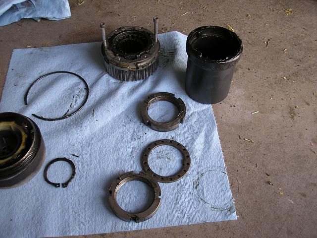
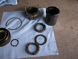 You can see in the picture the inner locknut (lower), retaining ring (middle) and outer locknut (top)
along with the socket that you use to take them out. The spindle is threaded at the end and the inner
locknut is screwed on to it. In the picure, you can see a small pin sticking out of the locknut on the
upper left hand side. There are coresponding holes in the retaining ring. Also on the retaining ring
is a small tab sticking inside. You can see it on the right hand side of the ring. This tab fits in a
notch in the spindle. However the inner lock nut ends up, it needs to have the pin line up with one of
the holes on the retaining ring. Since the ring has a tab that fits in the notch, it doesn't rotate.
Since the pin on the inner locknut fits in a hole in the ring, it now will not rotate either. The outer
locknut is there to keep the locking ring pressed against the inner locknut. Since the ring isn't
rotating, the outer locknut doesn't need anything special to stay where it is.
You can see in the picture the inner locknut (lower), retaining ring (middle) and outer locknut (top)
along with the socket that you use to take them out. The spindle is threaded at the end and the inner
locknut is screwed on to it. In the picure, you can see a small pin sticking out of the locknut on the
upper left hand side. There are coresponding holes in the retaining ring. Also on the retaining ring
is a small tab sticking inside. You can see it on the right hand side of the ring. This tab fits in a
notch in the spindle. However the inner lock nut ends up, it needs to have the pin line up with one of
the holes on the retaining ring. Since the ring has a tab that fits in the notch, it doesn't rotate.
Since the pin on the inner locknut fits in a hole in the ring, it now will not rotate either. The outer
locknut is there to keep the locking ring pressed against the inner locknut. Since the ring isn't
rotating, the outer locknut doesn't need anything special to stay where it is.
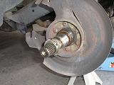
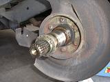 I took a picture with just the inner locknut on the spindle. You can see the pin sticking out right next
to the notch in the spindle. I then took a picture with the locking ring in place. You can see how the
tab fits in the notch and the pin fits in one of the holes in the locking ring.
I took a picture with just the inner locknut on the spindle. You can see the pin sticking out right next
to the notch in the spindle. I then took a picture with the locking ring in place. You can see how the
tab fits in the notch and the pin fits in one of the holes in the locking ring.
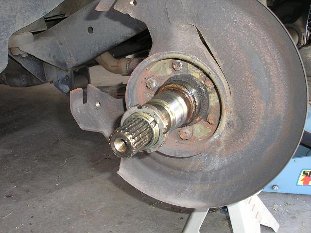
Once the locknuts are removed, you can pull off the rotor and hub, exposing the spindle. You can see how
the axle shaft sticks through the center of the spindle. If you pull the 6 nuts holding the spindle in
place (along with a bolt or two holding the dust shield in place) you can remove the spindle and have
access to the axle shaft and universal joint. In this picture you can also see the brake bracket. It's
nothing more than a stamped piece of plate steel with a couple of threaded holes to hold the brake
caliper in place.
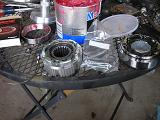
 Since I decided on new rotors and bearings, I didn't really have to check the condition of the old
bearings. Still, it's not a bad idea to do so just to see if there's any problems with the old set.
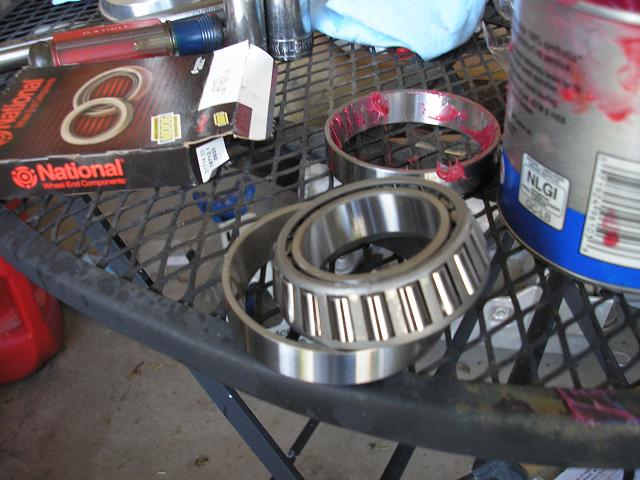
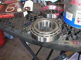
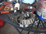
There are three basic parts to a bearing. The inner race, the bearing itself, and the outer race. The
race is the surface the bearing contacts. It is basically a solid piece of metal machined to very
exacting tolerances. It is removable so one can replace just the race rather than the entire part that
the race attaches to. The bearing is made up of several rolling pins held in place by a stamped metal
cage. When the two components move, the rolling pins reduces roll against the races and significantly
reduce friction. In the case of wheel bearings, the inner race and bearing stay together. The outer
race is not attached to the bearing in any way. The outer race is driven into the hub assembly. It's
slightly larger than the space made for it so that it is held in by friction after it's been driven in.
But it also means that putting it in requires a good bearing driver tool, a big hammer and a lot of elbow
grease. Wheel bearings are tapered. That means they are wider one one side than the other. There are
two bearings inside each hub. The narrow part of the tapers face each other. When you put the locknut
on, it presses the two bearings towards each other. The taper in the bearing keeps the wheel from
sliding side-to-side as you go around corners. The two pictures are of the bearing where you can see it
and a shot of it as it sits in the race. The race is pushed into the wheel hub and is a very tight fit.
The bearing fits loosely over the shaft so it can free spin.
Since I decided on new rotors and bearings, I didn't really have to check the condition of the old
bearings. Still, it's not a bad idea to do so just to see if there's any problems with the old set.
There are three basic parts to a bearing. The inner race, the bearing itself, and the outer race. The
race is the surface the bearing contacts. It is basically a solid piece of metal machined to very
exacting tolerances. It is removable so one can replace just the race rather than the entire part that
the race attaches to. The bearing is made up of several rolling pins held in place by a stamped metal
cage. When the two components move, the rolling pins reduces roll against the races and significantly
reduce friction. In the case of wheel bearings, the inner race and bearing stay together. The outer
race is not attached to the bearing in any way. The outer race is driven into the hub assembly. It's
slightly larger than the space made for it so that it is held in by friction after it's been driven in.
But it also means that putting it in requires a good bearing driver tool, a big hammer and a lot of elbow
grease. Wheel bearings are tapered. That means they are wider one one side than the other. There are
two bearings inside each hub. The narrow part of the tapers face each other. When you put the locknut
on, it presses the two bearings towards each other. The taper in the bearing keeps the wheel from
sliding side-to-side as you go around corners. The two pictures are of the bearing where you can see it
and a shot of it as it sits in the race. The race is pushed into the wheel hub and is a very tight fit.
The bearing fits loosely over the shaft so it can free spin.
The hubs I bought came with races already installed so I didn't have to put them in myself. But if you
have to do it, you really want to use the right bearing driver. The outer is pretty deep in the hub and
getting it in straight without the right tool is difficult, if not impossible. Take the time and use the
right tool to drive in the bearing race. If you don't get it right, your truck will never roll right and
you'll destroy the bearing.
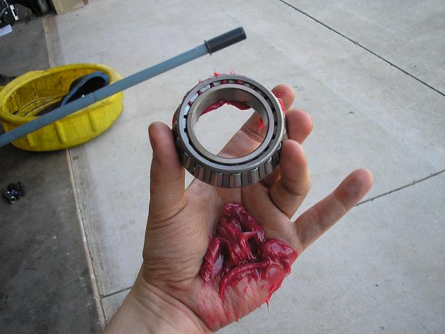
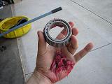 Bearings come dry but they need to be packed with grease before they are installed in the vehicle.
There's no getting around it, packing bearings with grease means you're getting your hands dirty. There
are tools to force grease into a bearing but for the shade tree mechanic who doesn't do this all the
time, they're not worth it. You need to get grease packed into the bearing pretty thoroughly. The
technique is to just put a blob of grease in your hand and then "shave" a bit off each time, pressing the
bearing into your hand. You need to drive grease all the way through until it starts coming out the
other side. You can see in the picture how the grease is just starting to come through the top side.
Bearings come dry but they need to be packed with grease before they are installed in the vehicle.
There's no getting around it, packing bearings with grease means you're getting your hands dirty. There
are tools to force grease into a bearing but for the shade tree mechanic who doesn't do this all the
time, they're not worth it. You need to get grease packed into the bearing pretty thoroughly. The
technique is to just put a blob of grease in your hand and then "shave" a bit off each time, pressing the
bearing into your hand. You need to drive grease all the way through until it starts coming out the
other side. You can see in the picture how the grease is just starting to come through the top side.
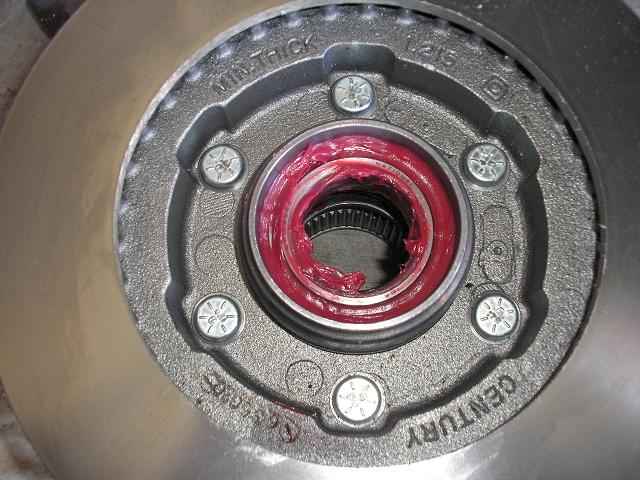
 I started with the inner bearing. I packed it with grease and dropped it in the hub. After putting it
in the hub, I loaded a layer of grease on either side of the bearing. It's a lot like laying down a line
of caulk but without the gun. Run your finger around the bearing to make sure you have a thick and even
coat. Go ahead and do it. Your hand is already greasy from putting the greasy bearing in. Do be
careful. There are machined edges inside the hub and they can be sharp. It's not hard to cut yourself
if you're not careful.
I started with the inner bearing. I packed it with grease and dropped it in the hub. After putting it
in the hub, I loaded a layer of grease on either side of the bearing. It's a lot like laying down a line
of caulk but without the gun. Run your finger around the bearing to make sure you have a thick and even
coat. Go ahead and do it. Your hand is already greasy from putting the greasy bearing in. Do be
careful. There are machined edges inside the hub and they can be sharp. It's not hard to cut yourself
if you're not careful.
 After I put the bearing in, I drove in the axle seal. You should never reuse an axle seal since you
damage it when you remove it. They're cheap. Go ahead and buy one. When you drive it in, use a piece
of wood that's bigger than the seal and hit it with the hammer. This will drive the seal in to place
but not too far. You want the edge of the seal to sit flush with the rim on the hub all the way around.
Be sure that the seal is sitting flush with the edge of the hub. If it's not installed straight, you
won't get the hub to sit straight on the spindle. Ask me how I know this. Take the time to get it
installed properly. I don't know if it's absolutely necessary to clean the grease before you put the
seal in but it probably is. Clean up any grease where the seal will sit inside the hub. It doesn't
take more than a minute or two to clean it up. And cleaning it properly will reduce the chances of
anything leaking.
After I put the bearing in, I drove in the axle seal. You should never reuse an axle seal since you
damage it when you remove it. They're cheap. Go ahead and buy one. When you drive it in, use a piece
of wood that's bigger than the seal and hit it with the hammer. This will drive the seal in to place
but not too far. You want the edge of the seal to sit flush with the rim on the hub all the way around.
Be sure that the seal is sitting flush with the edge of the hub. If it's not installed straight, you
won't get the hub to sit straight on the spindle. Ask me how I know this. Take the time to get it
installed properly. I don't know if it's absolutely necessary to clean the grease before you put the
seal in but it probably is. Clean up any grease where the seal will sit inside the hub. It doesn't
take more than a minute or two to clean it up. And cleaning it properly will reduce the chances of
anything leaking.
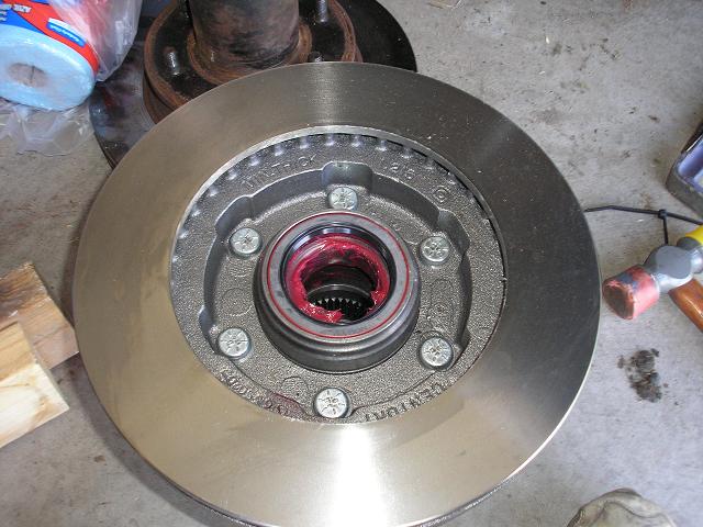
 Once I had the inner bearing and seal in place, I turned the assembly over and repeated the process with
the outer bearing. There is no seal to drive in with the outer bearing. It's held in by the locknuts and
it's sealed by the cap of the locking hub.
Once I had the inner bearing and seal in place, I turned the assembly over and repeated the process with
the outer bearing. There is no seal to drive in with the outer bearing. It's held in by the locknuts and
it's sealed by the cap of the locking hub.
I couldn't take a decent picture of the locknut assembly process. But it's pretty straightforward.
First thing is obviously to put the hub with the bearings onto the spindle. There's a good chance you'll
knock the outer bearing out of its seat when you do this. Don't worry. Just reseat it when you have it
in place. You should be more careful about not damaging the inner seal when you put it in. Just don't
hit it on anything when you're sliding the hub on and you're fine. Make sure you have the hub all the
way on. It doesn't take a lot of force to get it to seat on the spindle. Just make sure the brake
disc lines up about where it was before. In my case, there's just a thin space between the disc and
the dust shield.
Once you have the hub in place it's time to put the locknuts back on. Start with the inner locknut.
Make absolutely sure the pin is facing away from the bearing. I found it was easiest to use my index
fingers to start the nut. You never want to just line it up and drive it with anything. You always want
to start it by hand. If you cross thread this nut, you've just created a whole lot more work and expense
for yourself. The locknut should spin easily until it comes into contact with the bearing. Once it
does, use the socket to tighten it up. This is also when you want to pay attention and do it right.
Use the torque wrench here. Specs may vary but my manual says to torque the nut to 50 foot-pounds. It
also says to spin the hub while you're torquing it. You really do want to spin the hub while you do this
so the bearings seat properly. It's possible to torque the nut without spinning the hub but you get a
false reading. As soon as you spin the rotor, the bearings will slip around and the wheel will wobble
until you fix it. Save yourself the headache and spin the hubs. If you don't have a partner, you can
torque it just a little and spin, torque it a little more and spin, torque and spin, torque and spin,
until you get the proper reading.
After you torque the inner nut to spec, the manual has you back off the nut 1/8th of a turn. They have
you do this to make sure you seat the bearings but leave it loose enough to spin easily. Too much torque
and you have too much friction. So back the nut off 1/8 turn. That's 45 degrees or 7½ minutes on
the minute hand on a clock. Once you do that, you're ready to put the lockring back in. It only fits in
one position because of the tab and groove. And almost always, the pin in the inner locknut won't line
up with a hole in the ring. So you have to see how close it is to a hole, take out the ring, rotate the
nut to make it line up and put the ring back in. It may take more than one try. But don't continue
until you get it in solidly. Stick your fingers in and feel that the lock ring is seated flush against
the inner lock nut all the way around. If it rocks at all, it's not in all the way. Get in there and
tweak it until you get it to lie flat. Don't continue until you get this right. If you don't get it
right, the locknut isn't locked in place and you'll damage the bearings when it backs off. So get back
in there and do it right.
Go back and make sure the lockring is in place. Yes. It's that important.
Now that you're absolutely sure that the lockring is in place, put on the outer locknut. Start it by
hand like you did the inner locknut. Spin it on until it makes contact with the lock ring. Use the
torque wrench again and tighten it properly. Specs may vary but mine tells me 50 foot-pounds. This one
doesn't get backed off like the inner locknut. You just torque it and leave it.
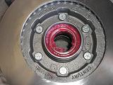
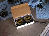 Once the locknuts are in place, you start putting the locking hub in place. I decided to splurge a
little on this rebuild. I bought a set of Warn Pemium lockout hubs to replace the factory original
parts. They're a little stronger than the factory parts and come with a lifetime guarantee.
Once the locknuts are in place, you start putting the locking hub in place. I decided to splurge a
little on this rebuild. I bought a set of Warn Pemium lockout hubs to replace the factory original
parts. They're a little stronger than the factory parts and come with a lifetime guarantee.
 You can see that the Warn parts are similar to the factory original. This is no coincidence since
Warn manufactured the OEM parts. From left to right in the picture is the lockring, internal hub, bag
with new screws and the snap ring and the cap. You can almost see the threads on the cap which turn the
engagement part. You can also see the wave spring that pushes the hub in when it is locked.
You can see that the Warn parts are similar to the factory original. This is no coincidence since
Warn manufactured the OEM parts. From left to right in the picture is the lockring, internal hub, bag
with new screws and the snap ring and the cap. You can almost see the threads on the cap which turn the
engagement part. You can also see the wave spring that pushes the hub in when it is locked.
I followed the manufacturer instructions to install the hubs. You start by putting the inner hub
assembly and the lock ring. Then you test to make sure you can slide the hub assembly in and out just
a little. If you can't, you didn't get the locknuts in properly. Go back and fix it. Yes. Go do it.
After you get it fixed, and get back to this step, you can continue. If it fits, put the snap ring into
the groove on the end of the axle shaft. In my case, the internal part of the locking hub is longer
inside to outside than the factory part. As a result, there isn't enough room for the snap ring on the
axle shaft. The instructions tell me that's acceptable. I guess I'll believe them. Once that's all
in place, make sure the cap is set to "Free" and put it in place. I find that putting one or two screws
through it helps to line it up. Start all 6 screws before you tighten any of them. These screws don't
require a lot of torque so don't crank down on them. Just get them snug.
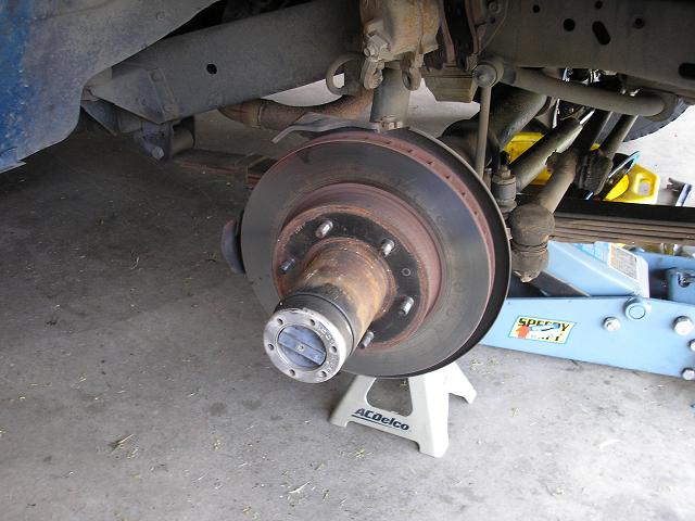
Once you have everything back together, use some brake parts cleaner and clean the rotor face. Any
grease or oil on the brake rotor and your brakes won't brake very well. If your setup is like mine,
there's only a small opening on the back since the rest is covered by a dust shield. So rotate the
rotor as you clean the back side of the disc.
 As I was working on putting everything back together, I discovered that the pistons in the brake
calipers were pretty badly rusted. A trip to the parts store and I had some remanufactured calipers.
Since I had the caliper paint laying around, I decided to give these parts a shot. There's no real
reason to paint your calipers but I just felt like doing it. They add a little bling to the truck.
If I ever swap from drum brakes to discs in the rear, I'll probably use up the rest of the caliper
paint on them.
As I was working on putting everything back together, I discovered that the pistons in the brake
calipers were pretty badly rusted. A trip to the parts store and I had some remanufactured calipers.
Since I had the caliper paint laying around, I decided to give these parts a shot. There's no real
reason to paint your calipers but I just felt like doing it. They add a little bling to the truck.
If I ever swap from drum brakes to discs in the rear, I'll probably use up the rest of the caliper
paint on them.
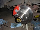
 For those eagle eye viewers, you'll notice the old caliper sitting on the tie rod in the background. The
parts store didn't have replacement brake lines in stock. I had to wait a day for the store to get a set
from the warehouse. So I left the old calipers attached until I'm ready to remove the old lines and
drain the fluid. I just wanted to get the caliper mounted and take a picture while I waited a day for
the new lines to arrive.
For those eagle eye viewers, you'll notice the old caliper sitting on the tie rod in the background. The
parts store didn't have replacement brake lines in stock. I had to wait a day for the store to get a set
from the warehouse. So I left the old calipers attached until I'm ready to remove the old lines and
drain the fluid. I just wanted to get the caliper mounted and take a picture while I waited a day for
the new lines to arrive.
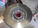
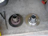
And just because people like to compare parts, I took a picture of the old hub and rotor next to the new
set.
Return to my J-10
 I started as one would always start by loosening the lug nuts while the tire was on the ground. I then
put the axle up on jack stands. And since it involves safety, I'm a "belt and suspenders" kind of guy so
I went ahead and left the jack under the axle. If the jack stand fails, the jack may keep the truck from
crashing down. After I got the truck in the air, I removed the tire and removed the 6 screws holding the
cap in place. They use standard allen head screws and they aren't in very tight. Removing them was easy.
I started as one would always start by loosening the lug nuts while the tire was on the ground. I then
put the axle up on jack stands. And since it involves safety, I'm a "belt and suspenders" kind of guy so
I went ahead and left the jack under the axle. If the jack stand fails, the jack may keep the truck from
crashing down. After I got the truck in the air, I removed the tire and removed the 6 screws holding the
cap in place. They use standard allen head screws and they aren't in very tight. Removing them was easy.